Tesla Model S: Remove Components For Access
Note: If possible, use the "From Below" procedure to remove and install the front drive unit (refer to procedure).
Special tools required for this procedure:
| Supplier | Part Number | Description |
| Tesla | 1054160-00-A | Support Jack, Front DU |
| Tesla | 1056360-00-A | Service Cover, Steering Rackg |
| Tesla | 1054946-00-A | Fluid Transfer Pan |
| Tesla | 1056542-01-A | Special 15mm Ratchet Wrench |
| Tesla | 1056566-00-A | Locating Shim Set, Front Motor |
| Bosch | 682-Q3MEC2T | 2 Ton Foldable Engine Crane |
| Tesla | 1056361-00-A | Oberg Tilt-Lift |
| Tesla | 1057312-00-A | Axle Extractor |
| Tesla | 1051629-00-A | Cap, Connection, Rosenberger, H4Z001-000/52 |
- Remove the front wheels (refer to procedure).
- Release the fasteners that secure the lower arch liners. Fold the arch liner forward to access the rear of the wheelwell.
- Lower the vehicle.
- Remove the 12V battery bracket beam (refer to procedure).
-
Release the 2 fir tree clips that secure the
12V positive harness to the front crossmember.

-
Move the 12V positive harness to the RH side of
the vehicle to keep it out of the working area.

-
Release the 4 bolts that secure the coolant
reservoir to the front crossmember (torque 6 Nm). Do not remove the
reservoir at this time.
.png)
-
Carefully lift up the coolant reservoir and
disconnect the coolant level sensor harness.
.png)
-
Ensure that the cap on the reservoir is
properly secured, then pull the reservoir forward into the underhood
area.
Note: The reservoir hose is routed behind the drive unit hose. Note the routing of the hoses and ensure that they are routed correctly during reinstallation.
.png)
-
Gently pull down on the 2 coolant hoses to
release the clips (x4) that secure them to the front crossmember.
.png)
-
Release the clip that secures the coolant
reservoir hose to the A/C line.
.png)
-
On the LH side of the 3-way fitting, clamp the
coolant hose that leads to the differential housing. Remove the hose
from the front drive unit and and plug the nipple.
.png)
.png)
-
Move the coolant reservoir to the LH side of
the vehicle and secure it out of the working area.
Caution: The reservoir is still secured to 2 coolant hoses.
.png)
- On the LH side of the drive unit, clamp the coolant hose. Remove the hose and plug the nipple. Tip: Use flexible hose clamp pliers to release the locking ring.
-
Move the clamped drive unit coolant hose to the
RH side of the vehicle so that it is out of the working area.

-
Release the clip that secures the LH A/C line
to the compressor HV harness.
.png)
- Release the 2 nuts that secure the A/C lines to the compressor. Plug both holes and cap both lines.
-
Disconnect the compressor LV harness.
.png)
-
Release the ground strap from the A/C
compressor bracket (torque 7 Nm).
.png)
-
Release the edge clip that secures the LV
harnesses to the compressor bracket.
.png)
-
Release the fir tree clip that secures the LV
harnesses to the top of the front drive unit.
.png)
- Wrap the LV harnesses around the RH hood strut so that they are out of the working area.
-
Have an assistant support the compressor.
Release the 3 bolts that secure the A/C compressor bracket to the
front drive unit (torque 10 Nm).
Caution: Do not spill any oil when removing the compressor.

-
Move the compressor and bracket to the RH side
of the vehicle and secure them outside of the working area.

- Raise the vehicle.
-
Release the nut that secures the sway bar end
links to the sway bar (torque 70 Nm).
.png)
-
Release the wheel speed sensor harness from the
brackets on the knuckle and the body.
-
Release the bolt that secures the upper control
arm to the knuckle (torque 60 Nm).
.png)
-
Temporarily lower the vehicle and remove the RH
halfshaft from the jackshaft.
Tip: Use a deadblow
hammer to separate the halfshaft.

- Raise the vehicle to access the RH wheelwell.
-
At the rear base of the RH wheelwell, release
and drain the coolant hose that leads to coolant pump 4.
Note: This is necessary because the coolant hose and pump are removed with the drive unit.
Hose highlighted in red

- Release any clips that secure the coolant hose to the body.
- Lower the vehicle to provide easier access to the underhood area.
-
Working from the underhood area, release the 2
bolts that secure the bracket for coolant pump 4.
Note: These bolts appear similar to other fasteners used in this procedure, but are slightly shorter. Ensure that the correct bolts are used during reinstallation.

- Release the straps that secure the lower RH section of the acoustic cover around the front drive unit. Remove only the lower RH section of the cover to access the drain plug.
-
Set the fluid transfer pan into position
beneath the drain plug. Ensure that the pan is level, then route the
drain hose between the subframe and aeroshield so that it will drain
into an oil drain pan.

- Remove the drain plug (torque 28 Nm).
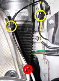
- Release the 2 bolts that secure each fuse box to the front crossmember (torque 5 Nm). Move both fuse boxes behind the front crossmember.
-
Release the bolt that secures the bracket for
coolant pump 3 (torque 6.5 Nm). Move the bracket behind the front
crossmember.

-
Release the 4 screws that secure the HV cables
to the front drive unit (torque 7 Nm).
Caution: During reinstallation, carefully inspect the connector seals. If any are damaged, replace them.
Caution: Apply P-80 emulsion to the connector seals on the HV cables before securing the HV cables during reinstallation.
Caution: Do not apply P-80 emulsion to the HV terminals.
.png)
- Disconnect the motor logic connector.
- On the LH side of the underhood area, release the bracket from the body that secures the 4-way valve.
- Hand-tighten the drain plug and remove the fluid transfer pan.
READ NEXT:
 Remove Front Drive Unit
Position the support jack on top of the front
crossmember and secure the 2 screws to the front crossmember.
The support jack mounts to the bolt holes on top of the fron
Front Drive Unit (From Above) (Remove and Install)
- Installation
Installation
Use alcohol wipes to clean the mating surfaces
between the RH motor mount and drive unit.
Ensure that the support jack is secured to the
front crossmember.
Front Drive Unit (From Above) (Remove and Replace)
Note: If possible, use the
"From Below" procedure to remove and replace the front drive unit
(refer to procedure).
Removal
Remove the front drive unit
(refer to procedure).
Transfer Compo
SEE MORE:
Side Applique - 2nd Generation - LH (Remove and Replace)
Removal
Partially raise the liftgate to access the back
of the applique.
Pull up on the back of the applique to release
the clips and remove the applique.
Add a mark to the underside of the applique to
indicate that is has been removed.
Cautio
Air Suspension - Pressurize - Full System
Add Nitrogen to the Air Reservoir System
Warning: Wear eye protection while performing this
procedure.
Caution: Tesla recommends using a nitrogen refill kit to
refill the air suspension reservoir. Do not use shop air, which
might contain contaminants that could damage the
