Tesla Model S: Front Drive Unit (From Above) (Remove and Install) - Installation
Tesla Model S (2012-2025) Service Manual / Front Drive Unit / Front Drive Unit (From Above) (Remove and Install) / Front Drive Unit (From Above) (Remove and Install)
- Installation
Installation
- Use alcohol wipes to clean the mating surfaces between the RH motor mount and drive unit.
- Ensure that the support jack is secured to the front crossmember.
- With an assistant, lower the motor on the crane while pushing it into the vehicle.
- Secure the straps around the motor.
- Slide coolant pump 4 and the hose back behind the motor; these will be reinstalled in a later step.
- Continue to lower the motor into position, both by lowering the crane and raising the support jack.
- Once the crane can no longer be lowered, ensure that the support jack straps completely support the drive unit, then release the crane cables.
- Continue to position the motor. Have an assistant working from the RH wheelwell help to align the motor with the RH motor mount.
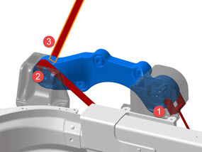
- Place the shear plate on the outboard side of the motor mount so that the shear plate bolt holes align with the motor mount bolt holes. Caution: Ensure that the bottom holes on the shear plate are not slotted. If the bottom holes are slotted, replace the shear plate with one that is not slotted.
- Loosely install the upper front bolt to secure the motor to the RH motor mount. Note: This allows for proper alignment of the motor.
- Install the lower RH section of NVH padding.
- Rotate the motor so that the other 3 bolt holes for the RH motor mount are aligned, but do not secure the bolts yet.
- Working from the underhood area, loosely install the lower front bolt.
- Working from the RH wheelwell, loosely install both rear bolts.
- Connect the harness for coolant pump 4. Caution: Ensure that the hose is not twisted.
- Secure the coolant pump bracket to the body. Note: These bolts appear similar to other fasteners used in this procedure, but are slightly shorter. Ensure that the correct bolts are used during reinstallation.
- Working from the RH wheelwell, resecure the cooling hose to the rocker hose.
- Have an assistant push the LH knuckle inboard while rotating it forward; install the LH axle. Caution: Do not damage the differential seal. Note: Ensure that the opening of the snap ring is facing towards the bottom of the drive unit. Note: Verify that the driveshaft is fully seated by carefully pushing it into the drive unit until there is an audible "click" from the snap ring.
- Resecure the LH knukcle to the upper control arm (torque 60 Nm).
- Working from the underhood area, set the LH motor mount into position and loosely install the front 2 bolts to secure it to the motor.
- Working from the LH wheelwell, loosely install the rear bolt to secure the mount to the motor.
- Tighten all 3 motor mount bolts (torque 38 Nm).
- Install the rear bolt and washer that secures the LH motor mount to the frame rail. Tip: It might be helpful to raise or lower the motor with the support jack to align the bolt.
- Install the front bolt and washer to secure the LH motor mount to the frame rail.
-
Position the 3 shim tools between the RH motor
mount and body.
Note: These tools ensure that both sides of the motor mount have at least 5 mm clearance to the body.
-
Working from the underhood area, position
the 2-pronged shim around the RH motor mount front bushing.

- Reach beneath the motor and position the hook shim tool between the mount and outer bushing.
- Reach downward between the V-brace and cross brace and position the straight shim tool between the mount and inner bushing.
-
Working from the underhood area, position
the 2-pronged shim around the RH motor mount front bushing.
- Working from the wheelwell, use a deep socket to install the rear bolt that secures the LH mount to the drive unit (torque 38 Nm).
- Working from the underhood area, install the 2 front bolts for the LH mount to the drive unit (torque 38 Nm).
-
Attach the 15 mm ratchet tool to a torque
wrench.
Caution: Ensure that the ratchet tool is 90 degrees perpendicular to the handle of the torque wrench when using the tool.

1 90 degree angle -
Working from the underhood area, fully torque
the 4 bolts that secure the motor to the RH mount (torque 75 Nm).

- Working from the underhood area, use the ratchet and torque wrench to secure the upper front bolt.
- Working from the wheelwell, secure the lower rear bolt.
- Working from the wheelwell, secure the upper rear bolt.
- Working from the underhood area, use the ratchet and torque wrench to secure the lower front bolt.
- Reinsert the shim tools to verify proper clearance between the bushings and body. If the shims do not fit, release the 3 bolts that secure the LH motor mount and repeat steps 25-27.
- Release the carabiners and remove the straps from the motor.
- Remove the support jack from the vehicle.
- Remove the fill plug (torque 28 Nm).
-
Fill the drive unit with the correct amount of
proper fluid:
- Use the fluid specified in General Information > Fluids and Capacities > Fluids .
- Use the amount specified in General Information > Fluids and Capacities > Fluid Capacities .
- Install the lower RH section of NVH padding.
-
Reinstall all components that were removed for
access:
- Remove the steering rack cover and reconnect the 3 steering rack harnesses.
- Reinstall the RH halfshaft.
- Secure the motor ground strap to the frame rail (torque 9 Nm). Note: Do not overtorque the nut to avoid breaking the stud on the frame rail.
- Reconnect the motor logic connector. Perform a push-pull-push test before proceeding to ensure that the connector is secure.
- Secure the bracket for coolant pump 4 to the front crossmember.
- Reinstall both fuse boxes.
- Reinstall the A/C compressor.
- Reinstall the 4-way bracket.
- Reinstall the A/C lines.
- Connect the LV A/C compressor harness and resecure the clip the motor.
- Secure the compressor ground strap.
- Reattach the 4 clips to secure the coolant hose to the bottom of the front crossmember, but do not secure the hoses to the motor at this time. Note: When securing the clips on the LH side of the front crossmember, do not use the front holes. These are for clipping the reservoir hose in a later substep.
- Route the coolant reservoir hose behind the hose for the differential housing, then clip the coolant reservoir hose to the front crossmember.
- Reconnect the coolant hoses to the differential housing and the RH side of the drive unit.
- Connect the coolant reservoir sensor.
- Secure the 4 bolts to reinstall the coolant reservoir to the front crossmember.
- Ensure that the coolant hose to the rear of the motor is clipped to the steering rack and subframe.
- Pull a vacuum on the A/C system for 15 minutes; continue this procedure while the vacuum is being pulled.
- Reconnect the clip to secure the A/C line to the hose.
-
Apply P-80 emulsion to the connector seals
on the HV cables, then resecure the HV cables to the motor.
Caution: Do not apply P-80 emulsion to the HV terminals.
Caution: Carefully inspect the connector seals. If any are damaged, replace them.
.png)
- Clip the 12V positive terminal to the top of the front crossmember.
- Install the 12V battery support brace.
- Reinstall the 12V battery tray.
- Hand tighten the bolt that secures the hose to the 12V battery support brace. and put the fir tree clips through the bracket.
- Resecure the fir tree clips that secure the LH A/C line to the bracket.
- Resecure the 2 bolts on the edges of the 12V battery support brace.
- Secure the 3 bolts that secure the 12V bracket to the front crossmember.
- Reinstall the long bolt in the back of the bracket.
- Reinstall the 12V battery and reconnect the 12V positive terminal.
- Recharge the A/C and resecure the ports.
- Resecure the intelligent battery sensor to the negative terminal, then reconnect the 12V negative terminal.
- Perform a coolant purge.
- Resecure the sway bar links.
- Reinstall all other components that were removed for access.
READ NEXT:
 Front Drive Unit (From Above) (Remove and Replace)
Note: If possible, use the
"From Below" procedure to remove and replace the front drive unit
(refer to procedure).
Removal
Remove the front drive unit
(refer to procedure).
Transfer Compo
Front Drive Unit (From Below) (Remove and Install) - Removal
Special tools required for this procedure:
Supplier
Part Number
Description
SEE MORE:
Canceling and Resuming
To manually cancel Traffic-Aware Cruise Control, press
the brake pedal or press the right scroll wheel on the
steering yoke.
To resume cruising, press the right scroll button.
NOTE: When Traffic-Aware Cruise Control cancels,
Model S does not coast. Instead, regenerative braking
slows down Model
Charge Settings
Access charge settings by touching Controls > Charging
when Model S is in Park.
When charging, you can also touch
the
charge icon on the touchscreen to access
charge settings.
1. Driving distance: Displays the total estimated driving
distance available.
2. Set limit: Adjust the charge limi
© 2019-2025 Copyright www.tesms.org
