Tesla Model S: Driveshaft Assembly - LH (Remove and Replace)
Warning: If the vehicle has air suspension, activate "Jack" mode on the touchscreen before raising and supporting the vehicle.
Special tool(s) required for this procedure:
| Supplier | Part Number | Description |
| Tesla | 1000991 | Axle Extractor Note: Use 1000991 for a large drive unit only. |
| Tesla | 1057312-00-A | Axle Extractor Note: Use 1057312-00-A for either a large or small drive unit. |
| Tesla | 1082171-00-A | S-hook |
- Position the vehicle in preparation for raising it, but keep the vehicle at ground level at this time.
- Ensure that the transmission is in Park.
- Remove the wheel center cap.
.png)
- Remove the hub nut (torque 245 Nm).
.png)
- Remove the wedge-lock washer.
- If the vehicle has air suspension, use Toolbox to depressurize the air spring back to the reservoir (refer to procedure).
- Sit in the driver's seat, but leave the driver's door open.
- On the touchscreen, touch Controls > E-Brake and Power Off.
- If there is an option for "Tow Mode", select it and skip to step 15. If not, continue with this procedure. Warning: Once "Tow Mode" is selected, the vehicle is in Neutral.
- Press and hold the brake pedal through step 14.
- On the touchscreen, touch "Press here for Neutral".
- On the touchscreen, touch "Power Off". A confirmation box appears.
- Touch "Power Off" on the confirmation box. The center screen turns off.
- Continue holding the brake pedal until hearing the sound of the contactors opening. Warning: The vehicle is now in Neutral.
- Raise and support the vehicle (refer to procedure). Warning: Do not work on an incorrectly supported vehicle. Warning: To avoid serious injury, use appropriate equipment to carry out this operation.
- Remove the mid aero shield (refer to procedure).
- Using a suitable tool, ease the brake caliper pistons and pads away from the rotor.
- Remove the bolts (x2) that secure the brake caliper to the knuckle (torque 120 Nm).
- Release the caliper and use the S-hook to support it.
Caution: To avoid damage to the brake line, the brake caliper must be supported at all times.
.png)
- Disconnect the electric parking brake harness connection.
.png)
- Remove the bolt that secures the upper suspension link to the knuckle (torque 140 Nm).
- Remove the nut and bolt that secure the air spring module to the
knuckle (torque 140 Nm).
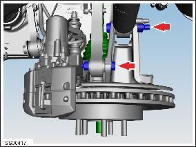
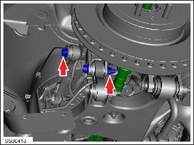
- Remove the bolt that secures the toe link to the knuckle (torque 130 Nm).
- Remove the nut and bolt that secures the integral link to the
knuckle (torque 130 Nm).
- Tap the exposed end of the driveshaft with a nylon mallet to release it.
- With assistance, swing the brake rotor and knuckle assembly
outward and release the outer driveshaft spline from the rear hub,
using a driver to disengage the axle from the hub splines.

- Tie the brake rotor and knuckle assembly aside for access.
- Use the axle extractor tool to release the driveshaft from the
transmission.
Caution: Ensure that the axle extractor tool does not contact any of the differential retaining studs.


- Carefully withdraw the driveshaft assembly from the vehicle.
Caution: To avoid damage to the driveshaft boots and oil seals, exercise caution when removing and installing drive shafts.
Caution: Plug the transmission opening to prevent ingress of dirt or moisture.
Note: Place suitable absorbent material around the affected area to absorb any fluid spillage.

Warning: Only use cleaning agents and solvents in a well-ventilated area.
Caution: Only fully tighten suspension nuts and bolts when the vehicle is on a 4-post lift and the suspension is in the ride height position.
Note: Clean the affected areas before installation.
Caution: Ensure that the bolt that secures the spring assembly to the knuckle is inserted towards the rear of the vehicle; the head of the bolt faces the front of the vehicle and the nut is tightened at the rear. Caution: Ensure that the new driveshaft has a snap-ring already installed. If it does not, then install a different driveshaft that has a snap-ring already installed. Return any driveshafts without a snap-ring using the MRB process. Do not remove or reuse snap-rings.

- Apply approximately 1 gram of Molykote M-77 Lubricant Paste
to the outboard side of the driveshaft to the hub mating face.

- When installing the driveshaft into the drive unit:
- Ensure that the opening of the snap ring is facing towards the bottom of the drive unit.
- Do not damage or displace the oil seal.
- Verify that the driveshaft is fully seated by carefully pushing it into the drive unit until there is an audible "click" from the snap ring.
- After connecting the electric parking brake caliper harness, wrap the connector seam with electrical tape to prevent dirt ingress.
- Pump the brake pedal at least 5 times to seat the pads against the brake rotors.
Warning: Always check that the brake pads are seated correctly before driving the vehicle.
- Repressurize the air spring.
- Transfer the vehicle to a 4 post lift (refer to procedure).
- Perform a four wheel alignment check (refer to procedure).
- Check for proper operation of the electronic parking brake.
READ NEXT:
 Charge Port - Single Phase - Non-Motorized (Remove and Replace) - Removal
Note: This procedure describes how to remove and install
the single phase charge port. If the vehicle is equipped with a 3
phase charge port, refer to procedure 44012102 (refer to procedure).
SEE MORE:
Instrument Panel - Driving
When Model S is driving (or ready to drive), the instrument panel shows your
current driving status and a real-time
visualization of the road as detected by the Autopilot components (see About
Autopilot). The
visualization automatically zooms in and out based on the detected road type.
NOTE: To
Solenoid - Air Suspension (Remove and Replace)
Removal
Raise and support the vehicle (refer to procedure).
Depressurize the air suspension (refer to procedure).
Access the solenoid.
For vehicles manufactured before November 2014, remove the
front aero shield (refer to procedure).
For vehicles manufac
