Tesla Model S: Charge Port - Single Phase - Non-Motorized (Remove and Replace) - Removal
Note: This procedure describes how to remove and install the single phase charge port. If the vehicle is equipped with a 3 phase charge port, refer to procedure 44012102 (refer to procedure).
Warning: The high voltage harness must be removed from the charge port before the charge port is removed from the vehicle. Never remove the charge port from the vehicle without first disconnecting the high voltage harness. Failure to follow this requirement may result in serious injury or death due to exposure to high voltage. Only Service Technicians that have received and completed high voltage training are authorized to perform this service.
Special tool required for this procedure:
| Supplier | Part Number | Description |
| Tesla | 1020288-00-A | TOOL,INSTALLATION,EV INLET,MDLS |
- Perform the vehicle electrical isolation procedure (refer to procedure).
- Remove the LH trunk trim (refer to procedure) .
- Remove the screw and release the clips (x2) from the HV inlet cover (torque 4 Nm).
- Remove the HV inlet cover.
Note: When the HV inlet cover is in the proper
position, a post on the cover presses a switch in the charge
port that activates the HVIL. The vehicle indicates a HVIL
fault if the cover is not properly installed or the post is
damaged.

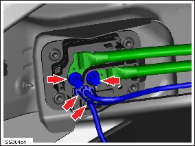
- Remove and discard the bolts (x2) that secure the HV cables to the charge port. Discard any washers that are installed between the bolts and the high voltage lugs.
- Disconnect the harness connectors (x2) from the charge port.
- Remove the lower nut that secures the charge port cable clamp to the body (torque 6 Nm).
- Remove the upper nut that secures the charge port cable clamp
(torque 5 Nm).

- Release the charge port clamp from the body and position the HV cables aside for access.
- Remove and discard the bolts (x4) that secure the charge port.

- Remove the charge port assembly.

READ NEXT:
 Charge Port - Single Phase - Non-Motorized (Remove and Replace) -
Installation
Charge Port - Single Phase - Non-Motorized (Remove and Replace) -
Installation
Installation
Installation procedure is the reverse of removal, except
for the following:
If the charge port has alignment pins, use wire-cutting pliers
o
Charge Port - Single Phase - Motorized (Remove and Replace)
Warning: Only technicians who have been trained in High
Voltage Awareness are permitted to perform this procedure. Proper
personal protective equipment (PPE) and insulating HV gloves with a
Charge Port - 3 Phase (Remove and Replace)
Note: This procedure describes how to remove and install
the 3 phase charge port. If the vehicle is equipped with a single
phase charge port, refer to procedure 44012202 (refer to procedure).
SEE MORE:
Starting/Discharging the System
Starting the System
Press the emergency stop button to disable HV systems.
Pull out the display/keyboard/trackpad tray.
Press the red power button to turn on the on-board PC.
Follow the onscreen instructions to log in to the system.
Userna
HV Junction Box - 2nd Generation (Remove and Replace)
Warning: Only technicians who have been trained in High
Voltage Awareness are permitted to perform this procedure. Proper
personal protective equipment (PPE) and insulating HV gloves with a
minimum rating of class 00 (500V) must be worn any time a high
voltage cable is handled. Refer
