Tesla Model S: HV Junction Box - Cover - 2nd Generation (Remove and Replace) - Removal
Warning: Only technicians who have been trained in High Voltage Awareness are permitted to perform this procedure. Proper personal protective equipment (PPE) and insulating HV gloves with a minimum rating of class 00 (500V) must be worn any time a high voltage cable is handled. Refer to Tech Note TN-15-92-003, "High Voltage Awareness Care Points" for additional safety information.
Removal
- Disconnect 12V and HV power:
- Rear wheel drive (RWD): Refer to procedure.
- Dual Motor: Refer to procedure.
- Remove the 2nd row seat frame:
- Standard seats: Refer to procedure.
- Executive seats: Refer to procedure.
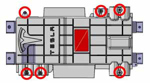
- Remove the HVIL bolt from the HVJB cover. Do not remove the
remaining fasteners at this time.
- North America, Japan (torque 4 Nm)
Note: In North American and Japanese vehicles, the HVIL bolt is one-time use only. Install a new bolt during reinstallation.

- Europe, APAC (torque 5 Nm)
Note: In European and APAC vehicles, the HVIL bolt can be reused during reinstallation.

- North America, Japan (torque 4 Nm)
Warning: Ensure that the multimeter and leads are capable of handling at least 500V.
- Remove the remaining fasteners that secure the HVJB cover.
- North America, Japan (torque 8 Nm)
Note: In North American and Japanese vehicles, there are 5 additional fasteners.

- Europe, APAC (torque 8 Nm)
Note: In European and APAC vehicles, there are 6 additional fasteners.
- North America, Japan (torque 8 Nm)
- Use a multimeter to check voltages across the HV cables and to
ground:
Warning: If any voltage reading is more than 10V, the high voltage contactors are not fully opened. Due to the risk of electrocution, contact Service Engineering before performing any further work.
Warning: Never use a fastener or an e-coated surface as a path to ground. In this procedure, ensure that the ground strap from the HVJB is secure to the body and use the lug as a path to ground.
- The 4 HV cables to the HV battery and rear drive unit
- The 2 HV cables to the forward junction box
- The 2 HV cables to the charge port
- Dual Motor vehicles only: The 2 HV cables to the front drive unit

Note: Vehicles with 3-phase charging have 4 harnesses to the charge port:1 B+ Front Drive Unit (if equipped) 2 B- Front Drive Unit (if equipped) 3 B+ battery/drive inverter 4 B- battery/drive inverter 5 B+ DCDC converter 6 B- DCDC converter 7 B- charge port 8 B+ charge port 
1 B+ N charge port 2 B- L1 charge port 3 B+ L3 charge port 4 B- L2 charge port
READ NEXT:
 North America and Japan only: Inspect the shield collar clamp
Insert the HVIL bolt into the shield collar clamp by 2 threads.
1
Install HVIL bolt 2
threads
HV Junction Box - Cover - 2nd Generation (Remove and Replace) -
Installation
Installation
Position the HVJB cover.
Install the HVIL bolt loosely. Do not tighten it fully at this
time.
North America, Japan
Note: In North American a
HV Junction Box - Reed Switch - 1st Generation (Remove and Replace)
Note: This procedure only applies to vehicles with the
1st generation High Voltage Junction Box.
Special tools required for this procedure:
Supplier
SEE MORE:
Unable to charge - Wall Connector issue
Wall Connector needs service
What this alert means:
Wall Connector hardware issue. Possible issues include:
Contactor not working
Self-test of internal ground fault monitoring circuit failed
Thermal sensor disconnected
Other hardware component issues
What to do:
An internal issue was detected
Brake Rotor - Rear - LH (Remove and Replace)
Warning: If the vehicle
has air suspension, activate "Jack" mode on the touchscreen before
raising and supporting the vehicle.
Special tool(s) required for this procedure:
Supplier
Part Number
