Tesla Model S: HV Junction Box - 2nd Generation (Remove and Replace)
Warning: Only technicians who have been trained in High Voltage Awareness are permitted to perform this procedure. Proper personal protective equipment (PPE) and insulating HV gloves with a minimum rating of class 00 (500V) must be worn any time a high voltage cable is handled. Refer to Tech Note TN-15-92-003, "High Voltage Awareness Care Points" for additional safety information. Removal
- Remove the high voltage junction box (HVJB) cover (refer to procedure).
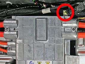
- Release the 2 HVJB harness connections from the master charger
by pressing on the tab on each connector. If the vehicle is equipped
with dual chargers, repeat this step for the harness connections to
the slave charger.

- Dual motor vehicles only: Mark the rear HV cable that leads to
the front drive unit as B-, and the forward HV that leads to the
front drive unit as B+.
Table 1: HV Cable fasteners inside HVJB

1 B+ Front Drive Unit (if equipped) 2 B- Front Drive Unit (if equipped) 3 B+ battery/drive inverter 4 B- battery/drive inverter 5 B+ forward junction box 6 B- forward junction box 7 B- charge port 8 B+ charge port - Release the 2 nuts that secure the HV cables that lead to the front drive unit (torque 9 Nm). Note: Refer to Table 1. Note: It is not necessary to replace the fastener(s) after it is removed. The threaded area has a reusable dry sealant, which looks similar to adhesive patch material.
- Mark the rear HV cables that lead to the battery and drive inverter as B‒, and the forward HV cables that lead to the battery and drive inverter as B+. Note: Refer to Table 1.
- Release the 2 nuts that secure the HV cables that lead to the battery and drive inverter (torque 9 Nm). Note: Refer to Table 1. Note: It is not necessary to replace the fastener(s) after it is removed. The threaded area has a reusable dry sealant, which looks similar to adhesive patch material.
- Mark the rear HV cable that leads to the forward junction box as B+ and the forward HV cable that leads to the forward junction box as B-. Note: Refer to Table 1.
- Release the 2 bolts that secure the HV cables that lead to the forward junction box (torque 4 Nm). Note: It is not necessary to replace the fastener(s) after it is removed. The threaded area has a reusable dry sealant, which looks similar to adhesive patch material.
- Mark the HV cables that lead to the charge port.
- Single-phase charging: Mark the forward cable as B- and the rear cable as B+.
- 3-phase charging: Starting from the front and working toward the rear of the vehicle, mark the 4 HV cables that lead to the charge port from front to rear as L2, L3, L1, and N.
Table 2: 3-Phase charge port cables

1 B+ N charge port 2 B- L1 charge port 3 B+ L3 charge port 4 B- L2 charge port - Release the bolts that secure the HV cables that lead to the
charge port.
- North America, Japan: 2 bolts (torque 9 Nm).
- Europe, APAC: 4 bolts (torque 4 Nm).
Note: It is not necessary to replace the fastener(s) after it is removed. The threaded area has a reusable dry sealant, which looks similar to adhesive patch material.
- Release the bolt that secures the ground strap to the rear of
the HVJB (torque 6 Nm).
Note: Leave the ground strap secured to the vehicle.
- Disconnect the low voltage harness connection on the rear LH
side of the HVJB .

- Release the 4 bolts that secure the HVJB to the body (torque 5
Nm). Remove the HVJB from the vehicle.

Installation procedure is the reverse of removal, except for the following:
- Before reinstalling the ground strap, clean the ground tab,
then apply a small amount of Penetrox A-13 electrical joint
compound to the ground tab.
- For the proper torque sequence of the bolts that secure the HVJB cover, refer to HV Junction Box - Cover - 2nd Generation (Remove and Install).
READ NEXT:
 HV Junction Box - Cover - 2nd Generation (Remove and Replace) - Removal
Warning: Only technicians who have been trained in High
Voltage Awareness are permitted to perform this procedure. Proper
personal protective equipment (PPE) and insulating HV gloves with a
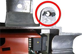
North America and Japan only: Inspect the shield collar clamp
Insert the HVIL bolt into the shield collar clamp by 2 threads.
1
Install HVIL bolt 2
threads
SEE MORE:
IP Carrier (Remove and Replace)
Warning: If the 12V power supply is disconnected, do
not attempt to open any doors with door glass in closed position.
Failure to follow this instruction could result in door glass
shatter.
Note: Before disconnecting the 12V power supply,
ensure that the driver's door window
Electrical system is unable to support all features
Shutting down features to conserve energy
The electrical system cannot support all vehicle features. Your vehicle is
shutting down nonessential features to
preserve energy for essential functions.
If you are driving when this alert is present, it is possible your vehicle may
shut down unexpected
