Tesla Model S: Slave Charger - LH - 2nd Generation (Remove and Replace) - Removal
Note: This procedure describes how to remove and install the 2nd generation slave charger. If the vehicle is equipped with a 1st generation slave charger, refer to procedure 44100102 (refer to procedure).
Warning: Only technicians who have been trained in High Voltage Awareness are permitted to perform this procedure. Proper personal protective equipment (PPE) and insulating HV gloves with a minimum rating of class 00 (500V) must be worn any time a high voltage cable is handled. Refer to Tech Note TN-15-92-003, "High Voltage Awareness Care Points" for additional safety information.
Warning: To avoid personal injury, eye protection must be worn while using compressed air.
Removal
Note: The slave charger is optional equipment. This procedure describes replacement of a failed slave charger. To install a slave charger in a vehicle that is only equipped with 1 charger, refer to Service Bulletin SB-13-44-010.
- Disconnect HV power, but leave 12V power connected. Perform the electrical isolation procedure (refer to procedure), except for the disconnection of the 12V battery ground.
- Connect an external charger to the 12V battery.
- Remove the 2nd row seat frame:
- Standard seats: Refer to procedure.
- Executive seats: Refer to procedure.
- Disconnect the connectors (x2) from the side of the slave
charger in the following order:
Caution: Disconnecting harnesses in the wrong order
triggers multiple high-priority alerts.
- Disconnect the 12-pin harness from the rear port.
- Disconnect the 10-pin HVIL loopback connector from the front port.

1 10-pin HVIL loopback connector 2 12-pin harness - Remove the HVJB cover (refer to procedure).
- Release the 4 harnesses that connect the HVJB to the chargers.

- Release all fasteners inside the High Voltage Junction Box (HVJB)
so that it can lifted up in order to replace the charger in a later
step:
- Dual motor vehicles only: Mark the rear
HV cable that leads to the front drive unit as B-, and the
forward HV cable that leads to the front drive unit as B+.
Table 1: HV Cable fasteners inside HVJB

1 B+ Front Drive Unit (if equipped) 2 B- Front Drive Unit (if equipped) 3 B+ battery/drive inverter 4 B- battery/drive inverter 5 B+ forward junction box 6 B- forward junction box 7 B- charge port 8 B+ charge port - Release the 2 nuts that secure the HV cables that lead to the front drive unit (torque 9 Nm). Note: Refer to Table 1. Note: It is not necessary to replace the fastener(s) after it is removed. The threaded area has a reusable dry sealant, which looks similar to adhesive patch material.
- Mark the rear HV cables that lead to the battery and drive inverter as B‒, and the forward HV cables that lead to the battery and drive inverter as B+. Note: Refer to Table 1.
- Release the 2 nuts that secure the HV cables that lead to the battery and drive inverter (torque 9 Nm). Note: Refer to Table 1. Note: It is not necessary to replace the fastener(s) after it is removed. The threaded area has a reusable dry sealant, which looks similar to adhesive patch material.
- Mark the rear HV cable that leads to the forward junction box as B+ and the forward HV cable that leads to the forward junction box as B‒. Note: Refer to Table 1.
- Release the 2 bolts that secure the HV cables that lead to the forward junction box (torque 4 Nm). Note: It is not necessary to replace the fastener(s) after it is removed. The threaded area has a reusable dry sealant, which looks similar to adhesive patch material.
- Mark the HV cables that lead to the charge port:
- Single-phase charging: : Mark the forward cable as B- and the rear cable as B+.
- 3-phase charging: : Starting from the front and working toward the rear of the vehicle, mark the 4 HV cables that lead to the charge port from front to rear as L2, L3, L1, and N.
Table 2: 3-Phase charge port cables

1 B+ N charge port 2 B- L1 charge port 3 B+ L3 charge port 4 B- L2 charge port - Release the bolts that secure the HV cables that lead to
the charge port.
- North America, Japan: 2 bolts (torque 9 Nm).
- Europe, APAC: 4 bolts (torque 4 Nm).
Note: It is not necessary to replace the fastener(s) after it is removed. The threaded area has a reusable dry sealant, which looks similar to adhesive patch material.
- Dual motor vehicles only: Mark the rear
HV cable that leads to the front drive unit as B-, and the
forward HV cable that leads to the front drive unit as B+.
- Release the 4 bolts that secure the HVJB to the body (torque 5
Nm).
Note: Do not remove the HVJB from the vehicle. It is only necessary to release the bolts so that the HVJB can be lifted up in a later step.
HVJB shown removed from vehicle, for clarity.

- Release the ground strap from the rear of the charger (torque 7
Nm).
Note: Leave the ground strap secured to the
vehicle.

- Dual motor vehicles only: Release the bolt that secures the fuse
bracket to the slave charger (torque 9 Nm).

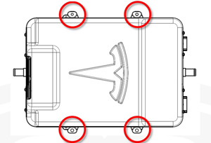
- Release the 4 bolts that secure the charger to the body (torque
7 Nm).
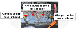
- Clamp the coolant hoses on both the inboard and outboard sides
of the charger, approximately 150 mm from the edge of the charger.

- Ensure that all harnesses and cables are protected from any coolant that might be spilled in a later step.
- Lift up the inboard side of the charger. Cover the floor of the vehicle with towels or shop rags to catch any coolant that might be spilled in a later step.
- Remove the coolant plug from the inboard side of the new charger and have it ready before performing the next step.
- Tilt the inboard edge of the charger upwards. Use pliers or a
similar tool to release the locking ring from the inboard coolant
hose. Remove the coolant hose from the new charger and immediately
install the coolant plug onto the old charger to stop coolant from
spilling out.

- Repeat steps 10-13 for the outboard coolant hose.
- Lift the charger out of the vehicle.
- If the charger is being shipped or stored, allow the coolant to drain from the charger, then use compressed air lightly to blow out any remaining coolant.
Caution: Do not exceed 25 PSI when using compressed air to blow out any remaining coolant.
READ NEXT:
 Installation, Configuration, and Coolant Purge
Fully clean the area before installing the new charger.
Note: Have an assistant hold up the front of the HVJB
20-30 mm until the coolant hoses have been secured to the charger.
Position
Master Charger - RH - 1st Generation (Remove and Replace)
Note: This procedure describes how to remove and install
the 1st generation master charger. If the vehicle is equipped with a
2nd generation master charger, refer to procedure 44102202 (refer
SEE MORE:
Disconnect 12V Power (RWD)
Warning: If the 12V power supply is disconnected, do
not attempt to open any doors with door glass in closed position.
Failure to follow this instruction could result in door glass
shatter.
Note: Before disconnecting the 12V power supply,
ensure that the driver's door window is
Buckle Assembly - 2nd Row - LH (Remove and Replace)
Warning: Prior to disconnection of 12 volt power supply,
ensure driver's door glass is in the fully open position. Failure to
follow this instruction could result in vehicle lockout.
Warning: If 12 volt power supply is disconnected, do not
attempt to open any doors with door glass in
