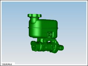
Tesla Model S: Master Cylinder and Reservoir Assembly (Remove and Install)
Note: This procedure applies to vehicles with the vacuum brake booster only. If the vehicle has the electromechanical brake booster assembly, the master cylinder and reservoir assembly are part of the brake booster assembly. Refer to procedure 33031402 (refer to procedure).
Caution: Use caution when handling the master cylinder assembly. Do not touch the outer edge of the primary piston.

Removal
- Disconnect 12V power (refer to procedure).
- Remove the wiper motor assembly (refer to procedure).
- Remove the underhood storage unit (refer to procedure).
-
Disconnect the coolant level sensor connector.

-
Release the nut that secures the coolant
reservoir upper bracket (torque 5 Nm).
.png)
-
Release the bolts (x2) that secure the coolant
reservoir to the crossmember (torque 5 Nm).
.png)
- Carefully move the coolant reservoir out of the working area. Note: Do not spill any coolant. Ensure that the reservoir cap is installed and that no hoses are disconnected.
- Remove the windshield washer reservoir (refer to procedure).
- Using a syringe, remove all fluid from the reservoir. Caution: Do not use a syringe that has been used for oils or other petroleum products. Caution: If brake fluid is spilled on a painted surface, wash off immediately with clean water. Note: Place suitable absorbent material around the affected area to absorb any possible fluid spillage.
- Disconnect the brake fluid level sensor connector.
-
Disconnect the brake booster vacuum sensor
connector.

-
Release the brake pipe unions (x2) (torque 18
Nm).
Caution: Plug pipe connections to prevent ingress of moisture or dirt.
Caution: If brake fluid is spilled on a painted surface, wash off immediately with clean water.
Note: Place suitable absorbent material around the affected area to absorb any possible fluid spillage.

-
Remove the nuts and washers (x2) that secure
the master cylinder to the brake booster (torque 25 Nm).

- Release the master cylinder and reservoir assembly from the brake booster. Caution: Ensure that the O-ring is not removed from the mating surface of the master cylinder during removal.
-
Remove the master cylinder and reservoir
assembly from the vehicle.
Installation procedure is the reverse of removal, except for the following:
Warning: Only use cleaning agents and solvents in a well-ventilated area.
Caution: Ensure that the O-ring is properly installed on the mating surface of the master cylinder before installation.

Bleed the brakes (refer to procedure).
READ NEXT:
 Master Cylinder (Remove and Replace)
Note: This procedure
applies to vehicles with the vacuum brake booster only. If the
vehicle has the electromechanical brake booster assembly, the
master cylinder is part of the brake bo
Brake Hose - Flexible - Front - LH (Remove and Replace)
Warning: If the vehicle
has air suspension, activate "Jack" mode on the touchscreen before
raising and supporting the vehicle.
Removal
Remove the front LH wheel
(refer
Brake Hose - Flexible - Rear - LH (Remove and Replace)
Warning: If the vehicle
has air suspension, activate "Jack" mode on the touchscreen before
raising and supporting the vehicle.
Removal
Remove the rear wheel arch liner
SEE MORE:
Position Sensor - Door - Exterior Handle - Front - LH (Remove and Replace)
Removal
Remove door handle for access (refer to procedure)
Remove door handle rear seal.
Remove control link pivot pin to allow control link to be
released from housing.
Position control link and remove screw securing position sensor
to link (torque 1 Nm).
Remove scr
Solenoid - Air Suspension (Remove and Replace)
Removal
Raise and support the vehicle (refer to procedure).
Depressurize the air suspension (refer to procedure).
Access the solenoid.
For vehicles manufactured before November 2014, remove the
front aero shield (refer to procedure).
For vehicles manufac
