Tesla Model S: HV Harness - Front Drive Unit to HVJB
Warning: Only technicians who have been trained in High Voltage Awareness are permitted to perform this procedure. Proper personal protective equipment (PPE) and insulating HV gloves with a minimum rating of class 00 (500V) must be worn any time a high voltage cable is handled. Refer to Tech Note TN-15-92-003, "High Voltage Awareness Care Points" for additional safety information.
Special tools required for this procedure:
| Supplier | Part Number | Description |
| Tesla | 1051629-00-A | Cap, Connection, Rosenberger, H4Z001-000/52 |
| Tesla | 10794924-00-A | Nylon Fish Tape, 25 ft. |
- Perform the vehicle electrical isolation procedure (refer to procedure).
- Remove the high voltage junction box (HVJB) cover (refer to procedure).
- Remove the front LH wheel arch liner (refer to procedure).
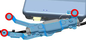
- Remove the bolt that secures the HV harness to the bracket in
the front left wheel arch (torque 4 Nm). Release the HV harness from
the bracket.

- Remove and discard the screws (x4) that secure the B+ and B- HV
cables to the front drive unit (torque 7 Nm).

- Release any push clips that secure the HV harness to studs on the bulkhead.
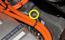
- Install protective caps over both HV cables to protect the terminals and seals.
- Secure the HV cables to the nylon fish tape tool using string or
fishing line.
Note: The nylon fish tape tool is used to pull and route the new harness through the channel during installation.
Note: Secure both HV cables together and slightly staggered to reduce the likelihood of one of them getting caught in the channel.
Note: The following image shows the HV cables without the protective caps installed.

- Lower the vehicle.
- Release the front of the LH C-pillar lower trim panel near the
base of the B-pillar.
Caution: Take care not to damage component(s).
.png)
- Fold the carpet inboard to expose the entrance to the channel
that runs along the left rocker panel.

- Gently pull the HV harness towards the rear of the vehicle and through the channel. Caution: Ensure that the string or fishing line is not accidently released from the HV cables while pulling the nylon fish tape tool through the channel.
- Once the HV harness is all the way through the channel, release the string or fishing line, but do not pull the nylon fish tape tool back through the channel or remove it from the vehicle.
- Disconnect the 12V connector from the HVIL switch.

- Remove the bolts (x3) that secure the fuse bracket (torque 9
Nm).
- Remove the bolt that secures the HV fuse ground to the body
(torque 5.5 Nm).
- Remove the nuts that secure the B+ and B- HV cables to the HVJB
(torque 9 Nm).
Note: It is not necessary to replace the fastener(s) after it is removed. The threaded area has a reusable dry sealant, which looks similar to adhesive patch material.

- Pull the front of the harness through the grommet between the seat base and 2nd row cabin.
- Remove the HV harness and fuse assembly from the vehicle.
Installation procedure is the reverse of removal, except for the following:
Caution: Replace all Patchbolt(s).
- Install protective caps over both HV cables to protect the terminals and seals when pulling the harness through the channel.
- Secure the new HV harness to the nylon fish tape tool using string or fishing line and, from the front LH wheel arch, gently pull the front of the nylon fish tape tool through the channel towards the front of the vehicle and retrieve the HV harness.
- Apply P-80 emulsion to the cable grommet at the rear entrance to the channel and ensure that grommet is fully seated.
- Apply P-80 emulsion to the connector seals on the HV cables
before securing the HV cables to the drive unit.
Caution: Do not apply P-80 emulsion to the HV terminals.
.png)
READ NEXT:
 HV Harness - Rear Drive Unit to HVJB
Warning: Only technicians who have been trained in High
Voltage Awareness are permitted to perform this procedure. Proper
personal protective equipment (PPE) and insulating HV gloves with a
Handle and Cable Assembly - 40A Wall Connector (Remove and Replace)
Note: This procedure describes how to remove and replace
the 40A Wall Connector handle and cable assembly. For instructions
on how to remove and replace the 80A Wall Connector handle and cable
SEE MORE:
Set Up HVAC Machine
Warning: Servicing must only be performed by personnel
familiar with both vehicle systems and the charging and testing
equipment. Always read and understand the HVAC machine operator's
manual before operating the HVAC machine.
Warning: R134a and R1234yf are hazardous liquids and, if
Charge Port - Single Phase - Non-Motorized (Remove and Replace) - Removal
Note: This procedure describes how to remove and install
the single phase charge port. If the vehicle is equipped with a 3
phase charge port, refer to procedure 44012102 (refer to procedure).
Warning: The high voltage harness must be removed from the
charge port before the charge port
