Tesla Model S: Charge Port - Single Phase - Motorized (Remove and Replace)
Warning: Only technicians who have been trained in High Voltage Awareness are permitted to perform this procedure. Proper personal protective equipment (PPE) and insulating HV gloves with a minimum rating of class 00 (500V) must be worn any time a high voltage cable is handled. Refer to Tech Note TN-15-92-003, "High Voltage Awareness Care Points" for additional safety information.
Warning: The high voltage harness must be removed from the charge port before the charge port is removed from the vehicle. Never remove the charge port from the vehicle without first disconnecting the high voltage harness. Failure to follow this requirement may result in serious injury or death due to exposure to high voltage. Only Service Technicians that have received and completed high voltage training are authorized to perform this service.
Special tool required for this procedure:
| Supplier | Part Number | Description |
| Tesla | 1020288-00-A | TOOL,INSTALLATION,EV INLET,MDLS |
- Disconnect 12V power.
- Rear wheel drive (RWD): Refer to procedure.
- Dual Motor: Refer to procedure.
- Remove the LH trunk trim (refer to procedure).
- Pull up on the tab on the front of the upper High Voltage cover,
then pull the rear of the cover inboard. Remove the cover.

- Release the 2 locking tabs to remove the lower HV cover.
Note: The following picture shows an older version, the newer version might have a sliding tab

- Use a multimeter to check voltages on the lugs that secure the
HV cables to the charge port:
- B+ to ground
- B- to ground
- B+ to B-

- Release the 2 bolts that secure the HV cables to the charge port (torque 9 Nm).
- Release the nut that secures the base of the HV cable bracket to
the body (5.5 Nm).

- Loosen the nut that secures the center of the cable bracket to
the body (torque 4 Nm).
Note: It is not necessary to fully release this nut.
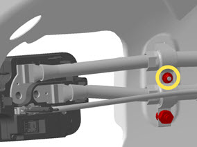
- Move the HV cables away from the charge port.
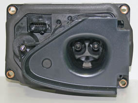
- Disconnect the 2 low voltage harnesses from the charge port.

- Release the 4 bolts that secure the charge port to the body
(torque 5 Nm), but do not remove it at this time.

- Disconnect the harness that leads to the charge port door motor.

- Remove the charge port from the vehicle.
Installation procedure is the reverse of removal, except for the following:
- Before installing the charge port, ensure that the grommet is fully seated in the door actuator.
- Ensure that the wires for the charge port door motor are
routed beneath the charge port.
Caution: Do not let the wires become pinched by the corner of the charge port.


- Ensure that the charge port is flush with the body panels.
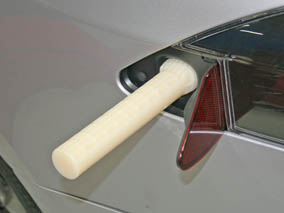
- Before securing the HV cables to the charge port, insert the
charge port alignment tool into the charge port.
- Ensure that both low voltage harnesses are fully seated.
- Ensure that both the upper and lower HV covers are fully seated.
- Test the charge port door for proper fit and operation. Adjust the charge port door as necessary.
- Perform a vehicle firmware update if a new charge port was installed. This ensures that the charge port's firmware is at the same revision as the vehicle firmware
READ NEXT:
 Charge Port - 3 Phase (Remove and Replace)
Note: This procedure describes how to remove and install
the 3 phase charge port. If the vehicle is equipped with a single
phase charge port, refer to procedure 44012202 (refer to procedure).
Release Cable
Note: This procedure describes how to manually release a
cable from the single phase charge port. If the vehicle is equipped
with a 3 phase charge port, refer to procedure 44013205 (refer to
SEE MORE:
Forward Junction Box (Dual Motor) (Remove and Replace)
Warning: Only technicians who have been trained in High
Voltage Awareness are permitted to perform this procedure. Proper
personal protective equipment (PPE) and insulating HV gloves with a
minimum rating of class 00 (500V) must be worn any time a high
voltage cable is handled. Refer
Striker - Seat back - 2nd Row Seat - LH (Remove and Replace)
Removal
Remove rear trunk side trim (refer to procedure)
Remove rear sill trim panel (refer to procedure)
Remove screws (x2) securing striker to body (torque 17 Nm).
Remove striker.
Installation
