Tesla Model S: Actuator - Mode (Remove and Replace)
Tesla Model S (2012-2026) Service Manual / Thermal Management / Actuator - Mode (Remove and Replace)
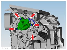
Removal
- Remove IP carrier (refer to procedure)
- Disconnect duct temperature sensor harness connector.
- Remove screw securing duct to HVAC assembly and position duct
aside (torque 1 Nm).

- Disconnect actuator harness connector.
- Remove screws (x3) securing mode actuator to HVAC assembly (torque 1 Nm).
- Note installed position of secondary flap link prior to removal.
- Remove air distribution mode flap actuator.
Caution: Take care not to damage component(s).
- Installation procedure is the reverse of removal, except for the following:
- Ensure secondary flap link is in correct position prior to installing actuator.
READ NEXT:
 Actuator - Front Passenger's Temperature (Remove and Replace)
Removal
Remove glove box assembly (refer to procedure)
Disconnect duct temperature sensor harness connector.
Remove screw securing duct to HVAC assembly, release from spigot
and p
Actuator - Defrost (Remove and Replace)
Removal
Remove glove box assembly (refer to procedure)
Disconnect actuator harness connector.
Remove screws (x3) securing defrost door actuator to HVAC
assembly (torque 1 Nm).
Motor - Fan assembly - HVAC (Remove and Replace)
Removal
Power the passenger seat fully rearward for access.
Remove the passenger footwell closing trim (refer to procedure).
Disconnect the fan harness connector and position the
SEE MORE:
Canceling and Resuming
To manually cancel Traffic-Aware Cruise Control, press
the brake pedal or press the right scroll wheel on the
steering yoke.
To resume cruising, press the right scroll button.
NOTE: When Traffic-Aware Cruise Control cancels,
Model S does not coast. Instead, regenerative braking
slows down Model
Pull Onto Flatbed Truck From Front
(Using Tow Eye)
NOTE: If Model S has no low voltage power, you need an
external low voltage power supply to open the hood or
use the touchscreen. See If Vehicle Has No Power.
CAUTION: To avoid damage, only pull the vehicle
onto a flatbed truck using a properly-installed tow
eye. Using the chassis, frame, or
© 2019-2026 Copyright www.tesms.org
