Tesla Model S: ABS Modulator Assembly (Remove and Replace)
Tesla Model S (2012-2026) Service Manual / Brakes / ABS Modulator Assembly (Remove and Replace)
Warning: If the vehicle has air suspension, activate "Jack" mode on the touchscreen before raising and supporting the vehicle.
Removal
- Remove the underhood storage unit for access (refer to procedure).
-
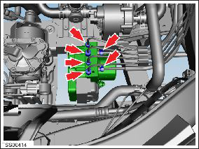
Release the brake pipes (x6) from the ABS
modulator (torque M10 14 Nm, M12 23 Nm).
Caution: Plug pipe connections to prevent ingress of moisture or dirt.
Note: Place suitable absorbent material around the affected area to absorb any possible fluid spillage.
- Remove the front skid plate (refer to procedure).
- Disconnect the ABS electrical connector.
-
Remove the nuts (x2) that secure the ABS
modulator to the damper bracket rubber mountings (torque 9 Nm).

- Lower the vehicle.
- Release the ABS modulator from the rubber mounting.
- Remove the ABS modulator from the vehicle.
Installation procedure is the reverse of removal, except for the following:
- Bleed the brakes (refer to procedure).
-
Use Toolbox to update or redeploy the firmware:
- If the vehicle is not running the latest firmware, run the "Vehicle Firmware Update" procedure.
- If the vehicle is running the latest firmware, run the "Firmware Redeploy" procedure.
- In Toolbox, perform the Stability Control (ESP) Program.
READ NEXT:
 Sensor - Wheel Speed - ABS - Front - LH (Remove and Replace)
Warning: If the vehicle
has air suspension, activate "Jack" mode on the touchscreen before
raising and supporting the vehicle.Removal
Remove the road wheel for access
(ref
Sensor - Wheel Speed - ABS - Rear - LH (Remove and Replace)
Warning: If the vehicle
has air suspension, activate "Jack" mode on the touchscreen before
raising and supporting the vehicle.
Removal
Raise and support the vehicle
(r
Brake Sensor Cluster - ESC (Remove and Replace)
Removal
Remove center console assembly
(refer to procedure)
Disconnect wiring harness connector.
Carefully cut acoustic padding coveri
SEE MORE:
Brake Caliper Pad Slides
Note: This is recommended for cold weather regions.
Note: Cleaning and lubricating the caliper pad
slides/abutments is not included in the Annual Service price.
Note: Perform the following steps on all 4 calipers.
Remove the pad retaining pins and collect the anti-rattle
spr
Pump - Windshield Washer Reservoir (Remove and Replace)
Removal
Remove the front LH upper wheel arch liner (refer to procedure).
Position a container to collect any spillage.
Disconnect the washer pump connector.
Release the washer tube from the pump and drain any fluid from
the reservoir.
Note: Place suitable abs
© 2019-2026 Copyright www.tesms.org
