Tesla Model S: Assembly - Top Pad - Instrument Panel (Remove and Install)
Warning: If the 12V power supply is disconnected, do not attempt to open any doors with door glass in closed position. Failure to follow this instruction could result in door glass shatter.
Note: Before disconnecting the 12V power supply, ensure that the driver's door window is fully open. Failure to follow this instruction could result in vehicle lockout.
Removal
- Open the glove box.
- Disconnect 12V power.
- Rear wheel drive (RWD): Refer to procedure.
- Dual Motor: Refer to procedure.
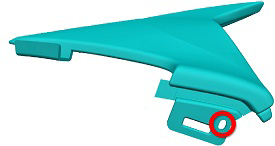
- Remove the instrument panel side covers (refer to procedure).
- Remove the screws that secure the sides of the top pad assembly
(torque 1 Nm).
- Remove the A-pillar middle trim panels (refer to procedure).
- Remove the A-pillar upper trim panels (refer to procedure).
- Remove the lower binnacle cover.

- Remove the screws (x2) beneath the lower binnacle cover that
secure the IP top pad to the IP carrier (torque 1 Nm).

- Lower the steering column and remove the steering column gap
hider by releasing the trim clips (x2).

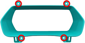
- Remove screws (x4) that secure the instrument cluster bezel
(torque 2 Nm).
Note: Components have been removed in this graphic to aid clarity.
- Remove the lower right instrument panel cover (refer to procedure).
- Remove the glove box (refer to procedure).
- In the upper area behind the glove box, remove the screws (x2)
that secure the passenger airbag to the crossbar beam (10 Nm).

- Locate the electrical connector on each side of the passenger
airbag.
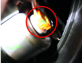
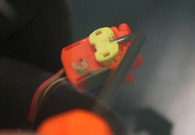
- Disconnect each harness connection by using a pick or similar
tool to pull out the latch on the connector.
- Cover the aluminum strips at the base of the top pad and around
the center screen with tape.
Caution: If the aluminum strips are not covered with tape,
they may be damaged when the top pad is removed in later
steps.

- Gently lift up on the rightmost edge of the instrument panel top
pad enough to allow room for a trim pry tool to release the
rightmost clip. Repeat this process working from right to left,
releasing one trim clip at a time until just to the right of the
center screen.
Caution: Take care not to damage component(s).
Note: Lifting with an inflatable wedge is recommended to reduce the risk of bending the top pad. Place the inflatable wedge above the vent outlet at the right side of the touchscreen.


- Gently lift up on the right side of the instrument panel top pad
(no more than 15 mm) and use a small wedge or other object to prop
up the right side of the top pad.
Caution: Take care not to damage component(s).

- Gently lift up on the leftmost edge of the instrument panel top
pad to allow room for a prying trim stick to release the leftmost
clip. Repeat this process working from left to right, releasing one
trim clip at a time until just to the left of the center screen.
Caution: Take care not to damage component(s).
Note: Lifting with an inflatable wedge is recommended to reduce the risk of bending the top pad. Place the inflatable wedge above the vent outlet at the left side of the touchscreen.

- Gently lift up on the left side of the instrument panel top pad (no more than 15 mm) and use a small wedge or other object to prop up the left side of the top pad. Caution: Take care not to damage component(s).
- Use a prying trim stick to release the trim clips directly above
the center screen.
Caution: Do not scratch or damage the PFC (printed flexible circuit) when releasing the trim clips above the center screen.


- Use a prying trim stick to release the remainder of the clips, alternating between the LH and RH sides. Caution: Take care not to damage component(s).
- With an assistant, lift the top pad and place it on a protective surface.
Caution: Take care not to damage component(s).
Installation- Installation procedure is the reverse of removal.
- Reinstalling the top pad requires two technicians: One technician presses down on the LH side of the top pad to secure the LH clips while the other technician presses down on the RH side to secure the RH clips. Working from the outer edges of the top pad inward, secure all the clips.
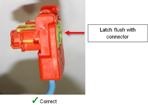
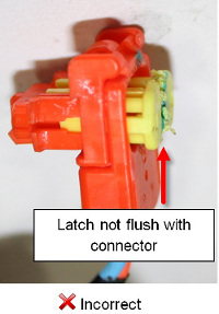
- After reconnecting each harness to the sides of the airbag,
press in on the latch so that it is flush with the face of the
connector. Gently try to pull the connector out again without
releasing the latch to ensure that the connection is tight.
- Follow the proper glove box reinstallation procedure (refer to procedure).
- After all procedures are complete, sit in the driver's seat and press the brake pedal to turn on drive rails. Ensure that the airbag safety indicator light exhibits normal operation: The light displays for 5 seconds during vehicle startup, then turns off.
Assembly - Top Pad - Instrument Panel (Remove and Replace)
Removal- Remove the instrument panel top pad assembly (refer to procedure).
- Remove the passenger's front airbag (refer to procedure).
Installation procedure is the reverse of removal.
