Tesla Model S: SIM Card - With SIM Extender (Remove and Replace)
Note: Vehicles in North America are not equipped with a SIM extender; this procedure only applies to vehicles outside of North America.
Removal
- Remove the center underhood apron (refer to procedure).
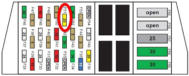
- Remove the cover from fuse box 2.
- Remove fuse F51.
Caution: The 12V battery is not supported when fuse F51 is disconnected. If fuse F51 is disconnected for more than 15 minutes, connect a float charger to the 12V battery.
Caution: Failure to remove fuse F51 can result in damage to the SIM card and/or the MCU.
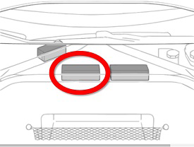
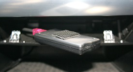
- Pull down the front of the storage compartment beneath the touchscreen.
- Release the SIM extender from the bottom of the touchscreen.
Caution: Do not attempt to completely remove the SIM extender from the vehicle.
Note: The SIM extender is attached to the bottom of the touchscreen with Dual Lock.
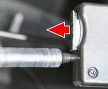
- Use a pen or a small pick to push the button on the SIM
extender. This releases the tray that holds the SIM card from the
extender. Remove the tray from the SIM extender.
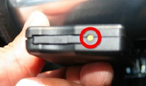
- Remove the SIM card from the tray.
Installation procedure is the reverse of removal, except for the following:
Caution: Ensure that the SIM card is seated properly. The side of the card with digits must face up inside the tray.
- Reboot the MCU.
- Ensure that the vehicle has cellular connectivity. If it does not, contact Service Engineering.
READ NEXT:
 SD Card - Media Control Unit (Remove and Replace)
Note: This procedure only applies to MCU/touch screens
that are revision E or later.
Removal
Remove the MCU/touch screen (refer to procedure).
Working from the top of the MCU
Camera - Forward Facing (Remove and Replace)
Warning: If the 12V power supply is disconnected, do
not attempt to open any doors with door glass in closed position.
Failure to follow this instruction could result in door glass
shat
Camera - Rear Facing (Remove and Replace)
Removal
Remove the tailgate lower finisher (refer to procedure).
Pull back the watershield for access to the rear camera
electrical connector.
SEE MORE:
HV Junction Box - 1st Generation (Remove and Replace)
Warning: Only technicians who have been trained in High
Voltage Awareness are permitted to perform this procedure. Proper
personal protective equipment (PPE) and insulating HV gloves with a
minimum rating of class 00 (500V) must be worn any time a high
voltage cable is handled. Refer
Adjusting Exterior Mirrors
Adjust the exterior mirrors by touching Controls >
Mirrors. Press the left scroll button on the steering yoke
to choose whether you are adjusting the Left or Right
mirror. Then use the left scroll button as follows to adjust
the selected mirror to its desired position:
To move the mirror up
